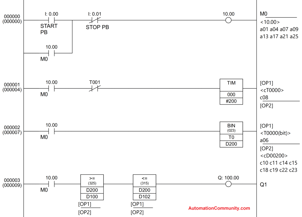
Programmable Logic Controllers (PLCs) often come with unnecessary features, complex software, and specialized code languages like Ladder Logic. This makes setting up a system difficult for most users and leads to much higher operating costs.
They make it hard in a few ways:
- Software Installation (Difficult to use, little to no compatibility)
- Confusing User Interface (Complex menus, Windows)
- Specialized Code Languages (Ladder logic, function block systems)

ControlByWeb Keeps It Simple
ControlByWeb controllers are a great drop-in solution for existing systems while being flexible enough to operate as standalone devices.
We make it simple in a few ways:
- Embedded Software (nothing to install, no compatibility issues)
- Easy-to-use User Interface (easy to follow, simplified menu structure)
- No-Code Logic (task builder)

How to Program a ControlByWeb No-Code PLC
In the following example, we will bench test a tank fill application using a relay and an analog input. We’ll use the X-412 which features 4 analog inputs and 4 relays. The X-412 is a versatile module that’s a great fit for measuring liquids. (Learn more about the X-412 here.)
We recommend performing a control bench test to ensure that the device will function as desired before completing a full onsite installation. The slope and offset for analog input devices can be configured here, but we suggest verifying the tank level once the final installation is finished.
First, connect your tank level sensor to the X-412. Then access the device using the IP address you’ve set. (Note that the default IP address for ControlByWeb relays is 192.168.1.2.) To access the device, input the IP address followed by /setup.html in your browser (e.g. 192.168.1.2/setup.html).
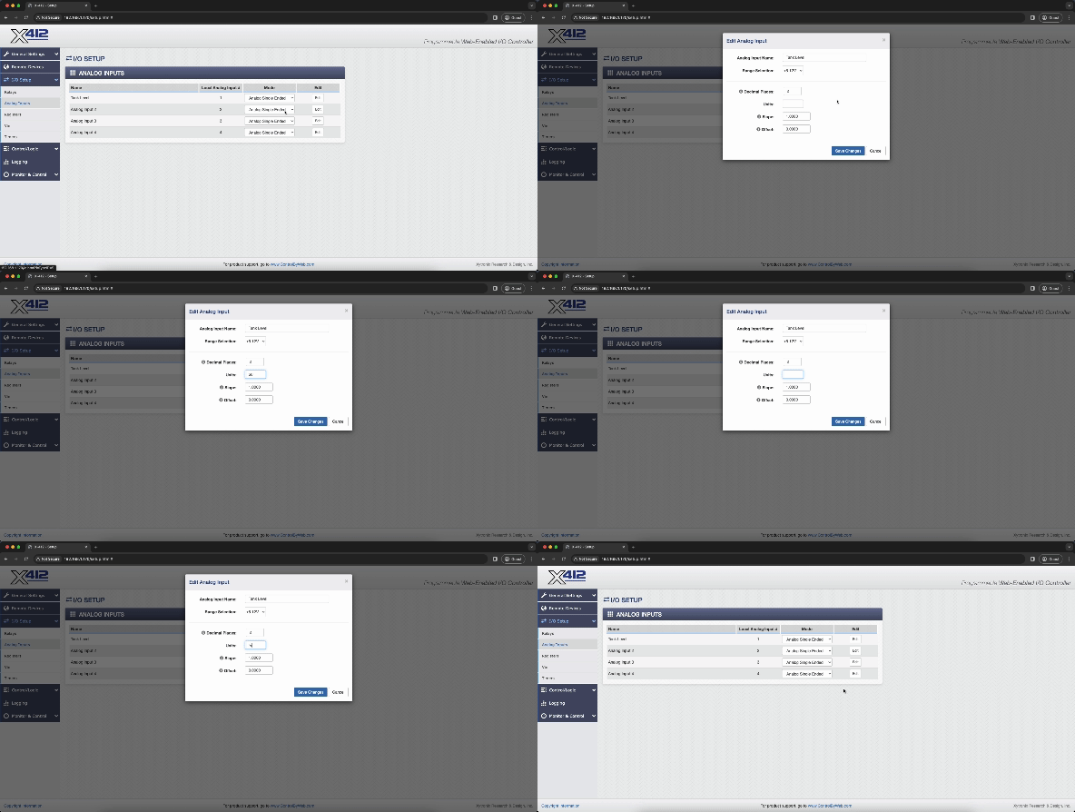
You’ll now see the on-board firmware. On the left-hand side of the screen, you will see I/O Setup, where you can change the name of a relay or analog input.

We changed the relay to “Pump 1,” and the analog input to “Tank Level.” In the edit window of the Tank Level input, you can enter a “%” symbol in the “Units” field. This will make setting up conditional tasks easier.
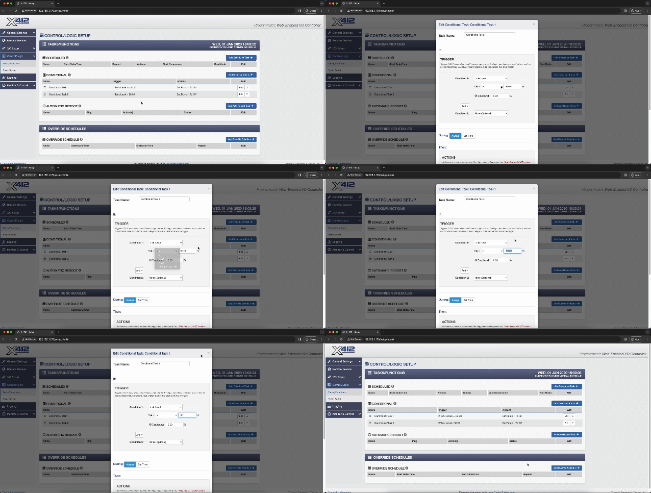
Because the value was set to call for a percentage, you can now enter at what percent the relay will trigger. For this, we set the values to 80% or above to turn the pump off, and 50% to turn the pump on.
In the “Control/Logic” tab on the left-hand side, click the blue “Add Conditional Task +” button to create a new conditional task. These tasks will be used to:
- Trigger the pump to turn off when the tank level is at or above 80%.
- Trigger the pump to turn on when the tank level is below 50%.

First, we will set up a conditional task to turn the pump off when the tank level is above 80%.
In the “IF” section, change Condition 1 to be:
- The “Tank Level” analog input
- Value to be “Equal to or Greater Than >”
- 80%
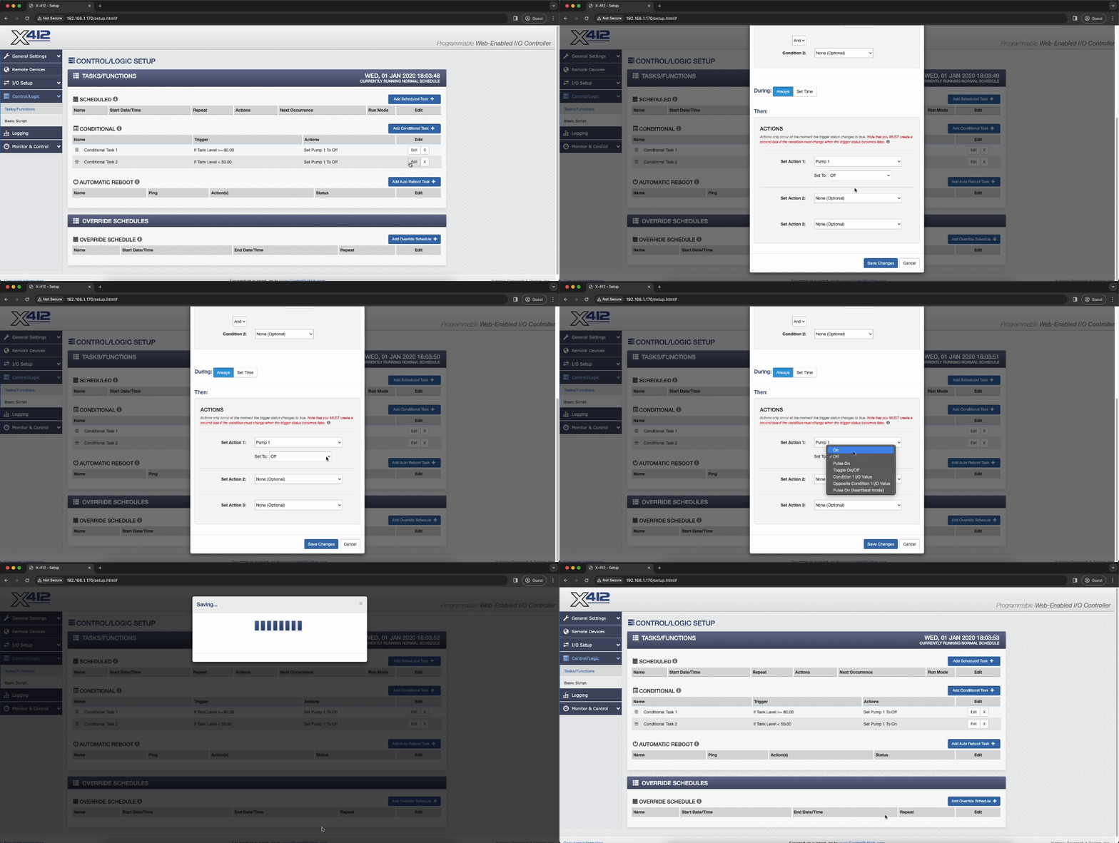
In the “During” section, set it to be Always.
In the “Then” section, change Action 1 to be:
- The “Pump 1” relay
- Set To “Off”
Next, we will set up a conditional task to turn the pump on when the tank level is below 50%.
In the “IF” section, change Condition 1 to be:
- The “Tank Level” analog input
- Value to be “Less Than <”
- 50%
In the “During” section, set it to be Always.
In the “Then” section, change Action 1 to be:
- The “Pump 1” relay
- Set To “On”
Once these tasks are set and all your information is in place (including the slope and offsets for your analog input), your control bench test should be setup, and when installed, your pump system will be fully automated. The state of the relays and inputs can be viewed on the control page by visiting the device at the IP that you’ve set it to (default 192.168.1.2).
The ControlByWeb Difference
For help with your industrial application, get in touch with our team or schedule a 15-minute demo to get a feel for our devices.
