X-404™ | Modbus RS-485 Module

$399.99$499.99

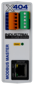
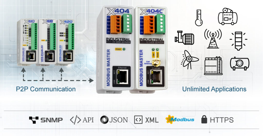
The X-404™ is purpose-built to monitor up to 32 Modbus RS-485 devices and/or sensors. It also includes a 1-wire bus for temperature and humidity monitoring.

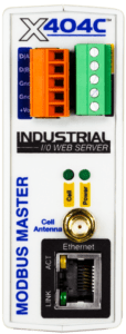
The X-404C offers wireless capability with a built-in cellular modem.

Modbus RS-485 input

Up to 16 temperature sensors

Cellular version available

Frequently Bought Together

Select a Cellular Data Plan

Cell plan prices are annual. Plans auto-renew on the anniversary of activation.

Total: $399.99
X-404 Overview

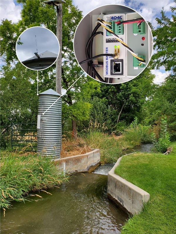
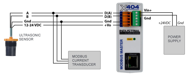
Monitor any sensor or equipment that has an RS-485 output with the X-404. It functions as a web-based, cloud-compatible Modbus master for third-party RS-485 modbus sensors and devices. This includes level, current , pressure, temperature, and humidity sensors.

X-404 Features

  • Email Notifications
  • Customizable Web-Based Dashboard
  • Peer-to-Peer Communication
  • Conditional Logging & FTP Log Exports
  • 400 Series Platform
  • Failover From Ethernet (X-404C Only)

X-404 Applications

  • Sensor & Equipment Monitoring
  • Generator Monitoring
  • Temp & Humidity Monitoring
  • Tank Level Monitoring

No WiFi Necessary

Cellular simplifies your installation and fits where no wired infrastructure exists. There’s no need for third-party resources or IT intervention—everything you need from a PLC is included with the X-404C.

Primary or Backup

With the X-404C, you have the option to use Ethernet as the primary connection to the network and cellular as a failover. This allows logging, remote access, and email alerts even if Ethernet fails.

Built-In Connectivity

The X-404C includes an omnidirectional antenna for use with the embedded LTE-M cellular radio. The antenna is FCC compliant and will not cause interference when installed correctly.

Configurable Status Page

The X-404C is powered by a lightweight, built-in user interface. Cellular devices have additional settings within the UI where users can review their signal strength, see registration status, set cellular mode and ping interval, and more.

No WiFi Necessary

Cellular simplifies your installation and fits where no wired infrastructure exists. There’s no need for third-party resources or IT intervention—everything you need from a PLC is included with the X-404C.

Primary or Backup

With the X-404C, you have the option to use Ethernet as the primary connection to the network and cellular as a failover. This allows logging, remote access, and email alerts even if Ethernet fails.

Power Your Whole Setup

Expansion modules have a ribbon-cable expansion bus that allows for shared I/O among ControlByWeb devices. It only requires one cellular-enabled PLC to enable all connected I/O to operate wirelessly.

Built-In Connectivity

The X-404C includes an omnidirectional antenna for use with the embedded LTE-M cellular radio. The antenna is FCC compliant and will not cause interference when installed correctly.

Configurable Status Page

The X-404C is powered by a lightweight, built-in user interface. Cellular devices have additional settings within the UI where users can review their signal strength, see registration status, set cellular mode and ping interval, and more.

Integration Icon

Integration Ready

We support HTTP GET, XML, JSON, SNMP, Modbus TCP/IP, and our Cloud API with more on the way.
No-Code Logic Icon

No-Code Programmable Logic

Our intuitive Task Builder empowers you to build custom logic using drop-down menus in an if-this-then-that flow.
Peer-to-Peer Icon

P2P Networking & Remote I/O

Devices can communicate through Peer-to-Peer (P2P) networking to share I/O among other ControlByWeb controllers, assign any device as master, set up multiple masters, and link remote inputs and relay control.

Email Notifications Icon

Email Notifications

Stay in control of operations with real-time monitoring. Add intelligence to your emails through programmable logic to instantly send notifications to the right people and eliminate false alarms.

Built-In Firmware Icon

Easy-to-Use Embedded UI

Our devices come with a simple embedded user interface that will enable you to easily monitor, manage, and control ControlByWeb PLCs from any standard web browser.

Data Logging Icon

Data Logging

Enjoy scheduled and conditional logging with email and FTP log exports. Add the optional ControlByWeb Cloud for remote access and downloadable logs.

Cloud Compatible Icon

Cloud Compatible

Enhance your capabilities with the ControlByWeb Cloud. Gain enhanced features such as simplified remote device access, data logging, and advanced analytics.

Security Icon

Trusted Device Security

Our controllers have no built-in OS or file system, making them less prone to vulnerabilities. Third-party consultants and government agencies test the cybersecurity of our controllers.

IIoT Icon

IIoT Monitoring & Control

Access the device directly through an assigned IP address. Set up your network settings the way you want, to limit or allow remote access through the cloud.

X-404 Case Studies


Specifications


Models
  • X-404-I: 9-28 VDC
  • X-404C-I-CA: 9-28 VDC
Power Requirements
  • Voltage:
    • X-404-I: 9-28 VDC
    • X-404C-I-CA: 9-28 VDC
  • Max Current:
    • No Modbus Sensors: 134mA
    • X-404 + 1.7A for modbus sensors: 1.834A

    See users manual for more information

RS-485 Connector
  • Sensors Supported: Up to 32
  • Connector: 5-position, removable terminal strip, 3.81 mm spacing
  • Communication: RS-485
Temperature Sensors
  • Maximum Number of Sensors: 16
  • Temperature Range: -67°F to 257°F (-55°C to +125°C)
  • Accuracy: ±0.5°C (from -10°C to +85°C)
  • Sensor Functions: Monitor Temperature, Log Temperature, Email Alerts, SNMP Traps
  • Humidity Type: ControlByWeb Model X-DTHS-P sensor
  • Humidity Range: 0-100% RH
  • Accuracy: ±2%
  • Max Cable Length: 600 feet (180m) maximum combined cable length
Real-Time Clock:
  • Manual or NTP(Network Time Protocol) setup
  • NTP Sync Period: Once, Daily, Weekly, On Powerup
  • Auto Daylight Savings Adjustment
  • Battery (capacitor) Power Backup

Capacitor Power Backup
  • Backup Functions: Real-time clock, 1 register, 2 counters, 64 relay states (remote modules only)
  • Backup Duration: 24 hours
Network
  • Type: 10/100 Base-T Ethernet Port
  • Setup: Static or DHCP IP address configuration
  • Wireless: Cellular Modem (X-404C-I only)
Connectors
  • Modbus Bus: 5-Position, 3.81mm terminal spacing, Removable. For 16-28 AWG wire.
  • Power and 1-Wire Bus: 5-Position, 3.81mm, Removable
  • Network: 8-pin RJ-45
  • Cell Antenna: Male SMA Connector (X-404C-I only)
LED Indicators
  • Number of LEDs: 3
    • Power on
    • Network linked
    • Network activity
Physical
  • Operating Temperature: -40°F to 150°F (-40°C to 65.5°C)
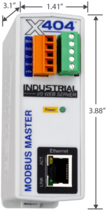
  • Size:
    • 1.41in (35.7mm) wide
    • 3.88in (98.5mm) tall
    • 3.1in (78mm) deep (not including connector)
  • Weight: 5 oz (142 grams)
  • Enclosure Material: Lexan 940 Polycarbonate Plastic
  • Enclosure Flame Rating: UL94 V0

Protocols
  • HTTP, HTTPS, XML, Modbus TCP/IP, SNMP, SMTP, Modbus RS-485
Logging
    • Log File Size: 3,072-Kbyte (up to 50,688 logs)
    • Storage: Nonvolatile Flash
    • Buffer Architecture: Circular Buffer

Log data can be periodically stored on a computer via FTP or email.

Advanced Features
  • Task Builder
  • BASIC interpreter (up to 4-Kbytes script file size)
  • Remote services
Password Settings
  • Password Length: 6-18 Characters
Electromagnetic Compliance
  • IEC CISPR 22, CISPR 24
  • EU EN55024, EN55022
  • X-404-I: FCC 47CFR15 (Class B)
Product Safety Compliance
  • IEC 61010-1

Manuals & Downloads


Firmware

400 Series Firmware v3.12 Patch Notes (PDF)

IMPORTANT: As a result of inline improvements to device hardware, different firmware versions have been created and are not cross-compatible. Installing the wrong firmware will not work. Please select the correct firmware for your current firmware version below:

X-404

X-404 Firmware v2.8.1(for firmware versions 2.8 or lower)

X-404 Firmware v3.12.2.5 (for firmware versions 3.0 or higher)

X-404C

X-404C Firmware v3.12.2.5 (for firmware versions 3.0 to 3.10)

X-404C Firmware v3.12.2.5 (for firmware versions 3.12 or higher)

Other Downloads

X-404 3D Model (.stp)

Accessories


24V DIN Rail Power Supply

24V DIN Rail Power Supply

Cloud Seat Icon

ControlByWeb Cloud Device Seat

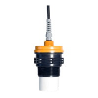
MNU-2424 Ultrasonic Sensor

MNU-2424 Ultrasonic Sensor

12VDC Power Supply

Power Supply | 12VDC

Vegapuls C 21 Non-Guided Radar Sensor

VEGAPULS C 21 Non-guided Radar

$1,125.00

View Product

For your convenience we have set up a live X-404 unit for testing and evaluation. By clicking the links below you have full access to this live unit. You can make changes to the configuration and settings through the setup pages and you can control X-404 through its control page. The control page allows you to change the state of the relay and view the current state of the input.

×

X-404™


Control Page Setup Pages*

*Setup page login information:

Username: admin

Password: webrelay

X-404 live demonstration setup

Live Demo With One of Our Sales Engineers

Let’s make it easy with a live demo and screen sharing.

Set up a one-on-one Q & A with one of our experts. We’ll help you find the best solutions for your next project and walk you through a demonstration.


Low on time? Watch a pre-recorded demo instead:

400 Series Setup and Programming Demo

X-404 Setup

The diagram illustrates how this demonstration is wired. Nothing is connected to the relay contacts; however, you can still turn the relay on and off to see how it works. The input state only changes when a voltage is applied to the input. For this demonstration, we have connected one of our X-332 controllers to the input of the X-404. You can apply a voltage to the input of the X-404 by accessing the control page for the X-332 (Digital Input Control Page).

Important Information

  • Multiple users may be accessing this device simultaneously so the device can change while you are using it.
  • This unit will be reset to factory defaults daily at 2:30AM MST.
  • Please DO NOT change network or password settings.

Related Products…

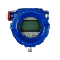
  • MND Modbus Display

    MND Modbus Display

    $503.31
    This user-friendly display is compatible with select ControlByWeb devices and does more than simply display its sensor’s readings. Features include the ability to alter sensor settings using the Modbus registry and to power a sensor with its batteries. Works on any Modbus network. *Cables and connectors not included.

    Easy 3-button programming

    RS-485: 9600 baud (Modbus RTU)

    Local display for up to 10 sensors

    Display: 5 digit LCD, 0.4 in. digits

    [frequentlyBought ids="7927,7929,6252"]

    View Product This product has multiple variants. The options may be chosen on the product page
Shopping Cart